Re-entry Tools and Modeling
Re-entry analysis and casualty risk assessment have become an important topic during the last few decades. Several space agencies and research institutes have developed a number of re-entry analysis tools to evaluate the trajectory and fragmentation process of any objects re-entering the Earth’s atmosphere. These tools verify the compliance with the applicable standards. Since analysis of re-entry flows is highly multidisciplinary, the following disciplines have to be treated[1],
- Flight dynamics of the object
- Analysis of the aerodynamic and aerothermal loads
- Analysis of the dynamic spacecraft behavior under external loads
- Analysis of the local heating and the resulting melting process
- Analysis of the mechanical loads and the relevant fragmentation and deformation processes
- Fragment tracking till ground impact
Space agencies across the world together with industrial support have developed several tools and analysis methods. These tools can be classified into two categories based on the analysis approach, they are (a) Object-oriented tools and (b) Spacecraft-oriented tools; These will be discussed in detail in the following section. A few examples can be,
- Free and Open Source Tool for Re-entry Analysis of Asteroids and Space Debris (FOSTRAD) [2]
- Debris Risk Assessment and Mitigation Analysis (DRAMA) [3]
- Debris Assessment Software (DAS) [4]
- Object Reentry Survival Analysis Tool (ORSAT) [5]
- DEBRISK [6]
- Spacecraft Aerothermal Model (SAM) [7]
- Spacecraft Atmospheric Re-entry and Aerothermal Breakup (SCARAB) [8]
- PAMPERO [9]
Object-oriented tools
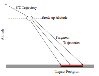
The main idea of the object-oriented approach is to simplify the vehicle geometry into basic shapes and analyze only individual parts of the spacecraft. These methods usually assume that at a certain altitude the spacecraft is decomposed into its individual elements. Their trajectories are independently followed using a 6 Degree of Freedom (DOF) or 3 DOF flight dynamic equations. For each critical element of the decomposed spacecraft, a destructive re-entry analysis is then performed. The concept of a fixed, common breakup altitude (see Fig.1) usually in the range between 75 and 85 km, allows determining a ground impact footprint for the surviving debris objects [1].
Among the above mentioned tools, DRAMA, DAS, ORSAT, DEBRISK, SAM, and FOSTRAD belong the object-oriented category. This approach uses simpler models of a spacecraft (primitive shapes) and its components, together with trajectory and aerothermodynamics calculations to model the demise, but allowing us to run fast and extensive parametric and statistical analyses. Therefore, object-oriented tools are usually adopted in the first project phases when multiple trade-offs at mission and system level have to be considered [3]. They provide valuable inputs for the definition of the mission and system architecture with initial identification of elements that are likely to survive the re-entry and that could be a risk for ground population and property. With this information, the system engineers can steer the spacecraft design towards safer solutions implementing mitigation measures early in the project development and save costs. To understand the overall concept of object-oriented tools in a better way, the examples in the following sections may be useful.
ORSAT
The Object Reentry Analysis Survival Tool (ORSAT) has been developed by NASA to determine when and if an object demises during reentry by using integrated trajectory, atmospheric, aerodynamic, aerothermodynamic, and thermal/ablation models [3][5]. It is important to note that the following information is older than a decade and new improvements are constantly being added into the codes. Nevertheless, the overall idea of the object-oriented codes can be clearly captured.
ORSAT analyzes the thermal destruction by melting during a ballistic re-entry for selected shapes of bodies and object motion assumptions. The object shapes and motions available in ORSAT are shown in the following Table.1 [1],
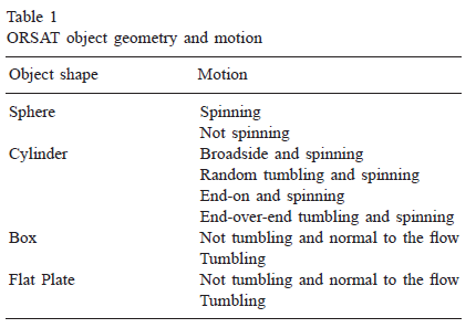
It considers thermal heating based on the lumped mass approach or one-dimensional heat conduction (upgraded to 2D conduction in ORSAT v6 [5]). Partial melting of objects is considered by a demise factor. All the material properties in the material database of ORSAT are temperature dependent. It is also limited to only ballistic, non-lifting reentry, and only tumbling motions or stable orientations of the body are allowed, which produce no lift. For boxes, cylinders, plates these are head-on, broadside or normal-to-flow orientations.
Due to the three-dimensional flight dynamics (upgraded to 6 DOF in ORSAT v6 [5]) the aerodynamic analysis has to provide only the drag coefficient. The aerodynamic analysis is based on the hypersonic limit ${Ma >1}$ with Mach number independence for blunt bodies. A distinction is made between the following three flow regimes:
- Free molecular flow: \(C_{D,fm} = f(Shape, Motion)\)
- Rarefied transitional flow: \(C_{D,trans} = f(Shape, Motion, Kn)\)
- Hypersonic continuum flow: \(C_{D,conti} = f(Shape, Motion)\)
A Knudsen number dependent bridging function is applied in the transitional flow regime[1]:
\[C_{D,trans} = C_{D,conti} + (C_{D,conti}-C_{D,fm})[sin(\pi[0.5+0.25\ln{Kn}])]\]The aero-heating law also distinguishes between these three flow regimes. An averaged shape and motion dependent heat flux to the surface is assumed. In hypersonic continuum flow the heat transfer formula for a spherical stagnation point of Detra, Kemp, Riddell is used as the primary basis [10]. The heat transfer rate is defined by,
\[\dot{q}_{st,conti}=\frac{110285}{\sqrt{R}} \frac{\rho_{\infty}}{\rho_{s1}} \frac{V_{\infty}}{V_{circ}}^{3.15}\]And the following equation is used for free molecular flow regime,
\(\dot{q}_{st,fm} = 0.5 \alpha \rho_{\infty} V_{infty}^3\); where, $\alpha$ is the thermal accommodation coefficient.
Shape-dependent effective radii of curvature and motion-dependent averaging factors are applied in order to use these equations for all object shapes and motion. The standard atmosphere model in ORSAT is the US Standard Atmosphere 1976. The Mass Spectrometer Incoherent Scattering Extended-1990 (MSISe-90) model is also available. There are only small differences between both models in the altitude regime below 120 km.
ORSAT also provides the possibility to define multiple breakup altitudes and the concept of aerodynamic and thermal mass. The aerodynamic mass is used for trajectory calculation whereas the thermal mass is used for the heating analysis. Due to this approach, heavy parent objects (aerodynamic mass) with light weighted shells (thermal mass) can be analyzed until the demise of the shells. Internal parts can be exposed to the flow subsequently at several calculated breakup altitudes.
Spacecraft-oriented tools
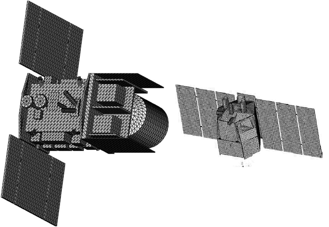
Spacecraft-oriented codes model the complete spacecraft as close as possible to the real design as one consistent object (See Fig.2). Aerodynamic and aerothermodynamic coefficients are calculated for the real, complex geometric shape, and not for simplified object shapes [1]. Breakup events are computed by analyzing the actually acting mechanical and thermal loads (i.e. breaking or melting into two more fragments). Shadowing and protection of spacecraft parts by others are taken into account. Therefore, the output represents a very detailed assessment, but requiring significant effort to build the spacecraft model and to perform the calculations. Spacecraft oriented tools are usually adopted in more advanced project phases, as the system definition gets into more details, to verify whether the mission and system design solution is compatible with the casualty risk requirements. SCARAB [8] and PAMPERO [9] are the only existing spacecraft-oriented tools available. Among these, PAMPERO developed by CNES is in the crucial validation phase.
SCARAB
Spacecraft Atmospheric Re-entry and Aerothermal Break-up (SCARAB) is designed to calculate the destruction of a spacecraft during a re-entry. The development started in 1995 and was conducted by Hyperschall Technologie Göttingen (HTG) within the frame of various ESA contracts.
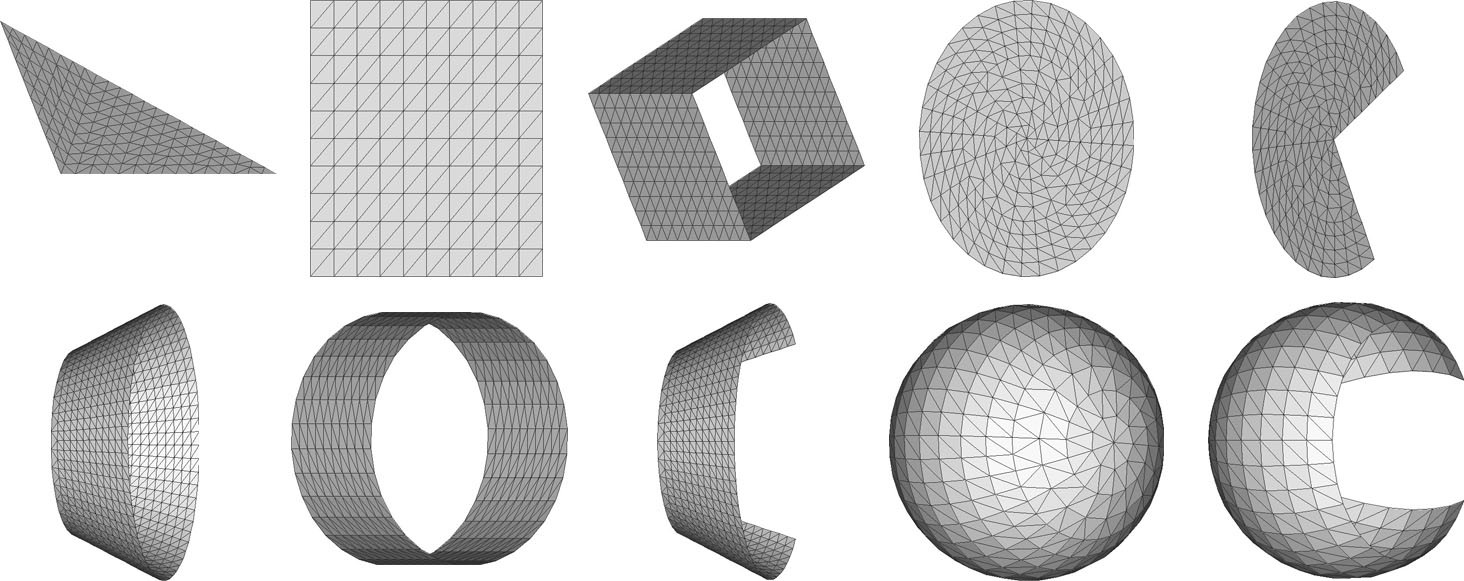
The geometry module of SCARAB provides panellized geometric primitives (see Fig.3), whose shape, position and size can be parametrically adjusted. This allows accurate reconstruction of the external and internal components of the spacecraft. Surface elements can be transformed into volume elements by specifying wall thickness. Complex shapes can be generated by combination of these shapes [8]. SCARAB is equipped with material data base in which most of the common materials used for S/C are included. For each material, 20 physical properties like heat capacity, conductivity, ultimate tensile stress, emission coefficient etc., are modelled with temperature dependence up to the melting point. SCARAB v2.0 also includes orthotropic and multilayered materials [8]. To match the real spacecraft, the physical model (provides basis for all the analysis modules) must follow the synthetic structure of spacecraft, starting with the top level (level 1) structure, and then modeling the subsystems (level 2 and lower). This ensures the physical model matches the physical data of the real spacecraft under study.
The analysis modules of SCARAB,
- Flight dynamics with 6 DOF
- Aerodynamic and aero-heating analysis
- Thermal analysis
- Structural analysis
- Destruction analysis by local melting or fracture
- Fragment tracking
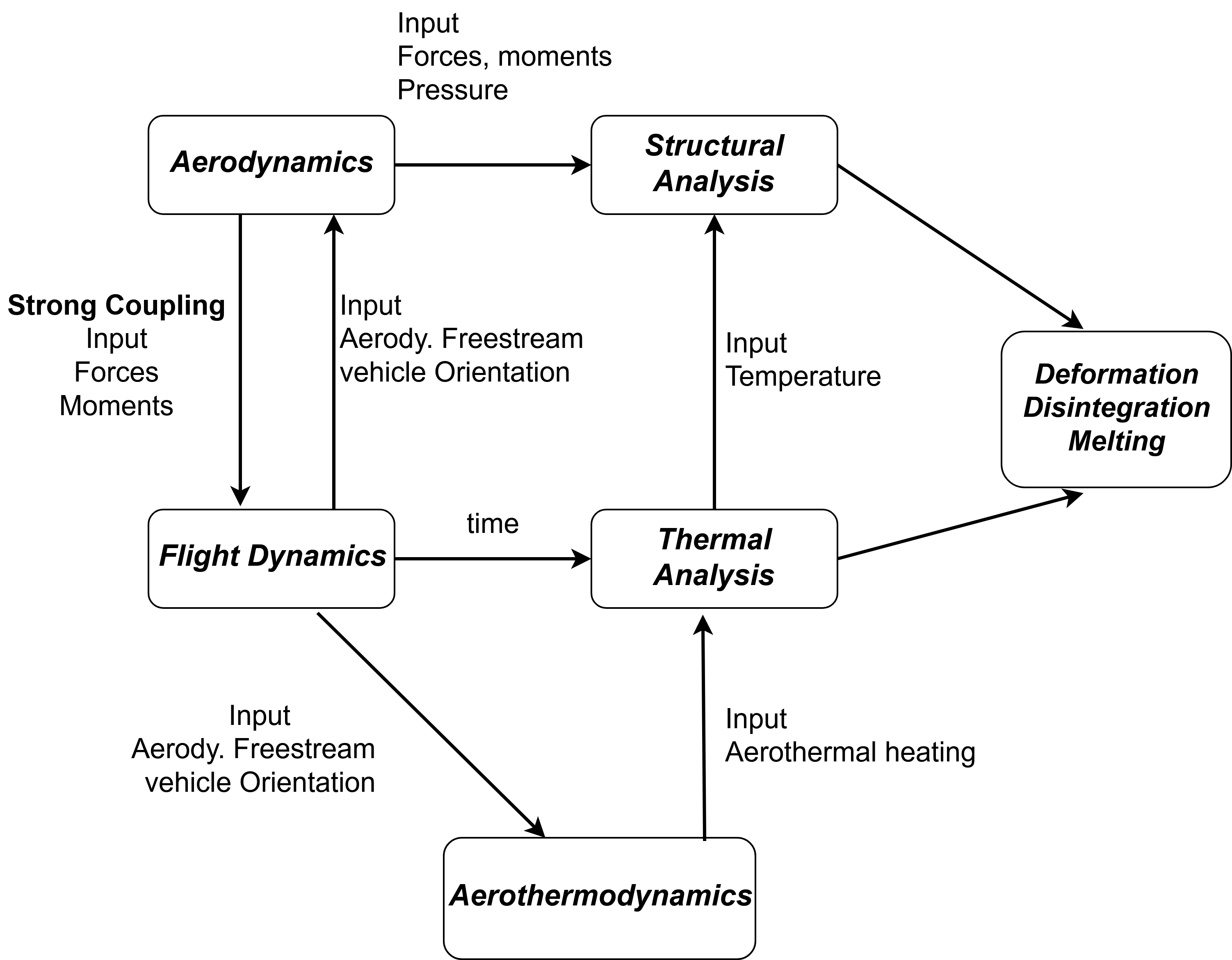
Between these modules, all the necessary communication links are established to accurately consider the coupling between these disciplines as shown in Fig.4. Analysis results along the trajectory are stored in history files. The re-entry analysis can be organized in chained loops, which allows for each time step of flight dynamics analysis, a new aerodynamic or aero-thermal analysis.
The trajectory and attitude motion of the S/C and of the fragments during melting phase is determined by numerical integration of 6 DOF equations of motion describing the change of momentum due to external force and torque. External forces and moments are due to gravity (earth, sun, moon) and due to aerodynamic pressure and shear stress. Integration with RK4 and fixed or variable step size. After the melting phase is completed (Ma <6), the flight dynamics of the fragments is tracked with a 3 DOF method till ground impact.
The aerodynamics is based on panel methods (Modified-Newtonian theory for hypersonic flows). This implies that, for each elementary surface panel, pressure, shear stress and heating rates are calculated. Integration over all the surface elements gives us the overall aerodynamic forces and moments.
\[\vec{F_{aero}} = q_{infty} \int_S (c_p \vec{n} + c_{\tau} \vec{t})dS\] \[\vec{M_{aero}} = q_{infty} \int_S (\vec{r}xc_p\vec{n} +\vec{r}xc_{\tau} \vec{t})dS\]The panel aerodynamics is applied in the hypersonic regime (Ma >5) and it distinguishes between several flow regimes. The aerodynamic coefficients are calculated based on empirical relations and on the consideration of shadow analysis (if main flow is shadowed by another surface, then the corresponding panel does not contribute to the resultant aerodynamic forces). In free molecular regime, the local pressure, shear stress are given by using accommodation coefficients as defined by Schaaf and Chambre [11]. The local heating rate based on Stanton number is calculated in the same way as pressure and shear stress. In hypersonic continuum regime, a modified Newtonian method is applied for surface pressure and skin friction is set of zero, which is acceptable for blunt bodies. Continuum heating is related to the stagnation point Reynolds number and the local inclination of the surface element. In rarefied transitional flow regime, the local aerodynamic coefficients and heat transfer rates are calculated with local bridging functions (bridges between continuum and free molecular regimes) which are validated with experimental data.
For thermal analysis, SCARAB relies on S/C geometry consisting of shell type elements. The heat flow balance equation considers conduction, radiation and aerodynamic heat flux (convective). If the thermal conductivity of a panel material is very high or the panel thickness ‘s’ is very small then, the temperature gradients in the panel can be neglected and the panel heating rate becomes,
\(q^{\prime} = \rho c_P s \frac{dT}{dt}\) for $T > T_{melt}$
If the melting point is reached then, the panel temperature stays at T_{melt} and the heat flux into the panel will melt the panel from the outer surface. Thereby, decreasing the solid wall thickness.
\(q^{\prime} = \rho h_{melt} \frac{ds_m}{dt}\) for $T = T_{melt}$
where, $s_m$ denotes the thickness of the melt layer. $s_m = s $ when the panel is completely molten. After the panel melts, the panel liquid mass is assumed to be blown away from the vehicle. Also, thick panels can be divided into N layers to perform thermal node analysis. Connectivity between the components will be updated to be lost when the corresponding panels are molten. During melting, S/C looses mass and several internal surfaces may be exposed to the flow. All these changes are communicated between different modules. SCARAB automatically considers the change of mass, shift of center of mass, and change of moment of inertia matrix.
Simple objects can be deformed in complicated ways, so full structural is not possible and is deemed computationally very expensive. Therefore to model mechanical fragmentation, stress and fracture analysis is simplified and restricted to be carried out in predefined cut planes (SCARAB v1.5). Elementary elements are joints and sections, which are positioned within a cur plane. The code then determines the differential loads resulting from the aerodynamic forces and inertial forces and conducts a stress analysis.
\[\sigma = \frac{F_x}{A}+\frac{M_yz}{J_y}+\frac{M_zy}{J_z}\]\(\tau = \frac{M_x\rho}{J_{\rho}}\) and the fracture condition is given by,
\[\sigma_{eq} = \sqrt{\sigma^2 + 3\tau^2} \geq \sigma_{ult}(T)\]The reduction of ultimate material stress with element temperature, at the cut plane is considered during the simulations. In SCARAB v2.0, in addition to the above discussed method, a finite element analysis method for thin shells has been implemented. The fragmentation tree is automatically generated and individual fragments are pursued to next break-up, till their full demise or till they reach the ground.
References
[1] Lips, Tobias, and Bent Fritsche. “A comparison of commonly used re-entry analysis tools.” Acta Astronautica 57.2-8 (2005): 312-323.
[2] Falchi, Alessandro, et al. “FOSTRAD: An advanced open source tool for re-entry analysis.” 15th Reinventing Space Conference. 2017.
[3] Fuentes, Irene Pontijas, et al. “Upgrade of ESA’s Debris Risk Assessment and Mitigation Analysis (DRAMA) tool: Spacecraft Entry Survival Analysis Module.” Acta Astronautica (2017).
[4] Opiela, J., and Nicholas L. Johnson. “Improvements to NASA’s Debris Assessment Software.” (2007).
[5] Dobarco-Otero, J., et al. “The Object Reentry Survival Analysis Tool (ORSAT)-version 6.0 and its application to spacecraft entry.” Proceedings of the 56th Congress of the International Astronautical Federation, the International Academy of Astronautics, and International Institute of Space Law, IAC-05-B6. Vol. 3. 2005.
[6] Omaly, Pierre, Christophe Magnin Vella, and Stephane Galera. “DEBRISK, CNES tool for re-entry survivability prediction: validation and sensitivity analysis.” Safety is Not an Option, Proceedings of the 6th IAASS Conference. Vol. 715. 2013.
[7] Beck, J., et al. “Progress in hybrid spacecraft/object oriented destructive re-entry modelling using the SAM Code.” 7th European conference on space debris, Darmstadt. 2017.
[8] Koppenwallner, Georg, et al. “Scarab-a multi-disciplinary code for destruction analysis of space-craft during re-entry.” Fifth European Symposium on Aerothermodynamics for Space Vehicles. Vol. 563. 2005.
[9] Annaloro, Julien, et al. “Elaboration of a new spacecraft-oriented tool: Pampero.” Proceedings of the 8th European Symposium on Aerothermodynamics for Space Vehicles. 2014.
[10] Detra, R. W. “Addendum to’Heat Transfer to Satellite Vehicles Reentering the Atmosphere’.” Jet Propul. 27 (1957): 1256-1257.
[11] Schaaf, S. A., and P. L. Chambre. “Flow of Rarefied Gases, High Speed Aerodynamics and Jet Propulsion.” Fundamentals of Gas Dynamics. Vol. 3. Princeton University Press NY, 1958.