Space Robotics: On-Orbit Servicing and Active Debris Removal
Active Debris Removal (ADR)
Space Debris is an ever increasing problem. This can be seen from the graph below showing the population of objects in Low Earth Orbit (LEO) over time:
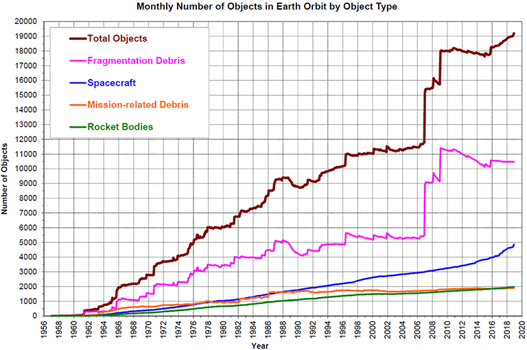
If the amount of objects keeps increasing at this rate, orbits might become unusable for future science and commercial missions. Due to this, several steps have to be taken to capture and de-orbit various unusable objects in Earth orbit such as spent rocket stages, dysfunctional satellites, etc. Methods for debris removal have been researched extensively in the available literature (see Kaplan, 2009). Without going into much detail, ADR methods can be categorized as shown in the figure below:
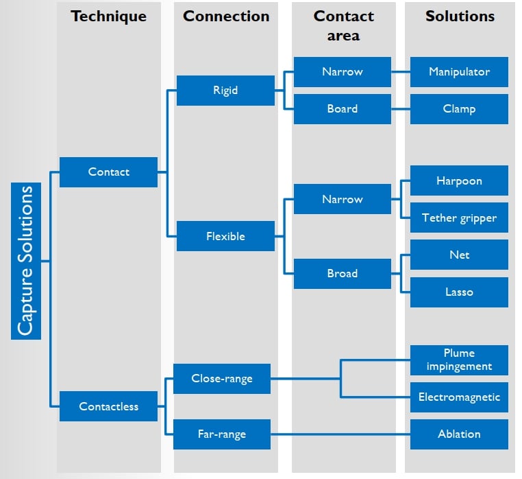
From these multiple methods, the focus of the Stardust-R project will be on robotic manipulators to actively remove space debris components such as dysfunctional satellites or rocket upper stages. In this wiki, the solutions involving manipulator will be studied in detail to actively remove space debris. The motivation for using a manipulator for removing space debris is that the developed technologies are transferable to On-Orbit Servicing (OOS) missions.
On-Orbit Servicing (OOS)
Robots have been used to capture, deploy, and service satellites in space. However, until now these have been teleoperated either by the astronauts in space or from the ground. Astronaut time in space is a scarce resource and their time availability limits the tasks that can be performed by robots. Similarly, ground control of the robots is extremely difficult due to time delays and periodic loss of communications. Thus, the development of technologies that automate the tasks of on-orbit servicing is crucial.
Past and Future
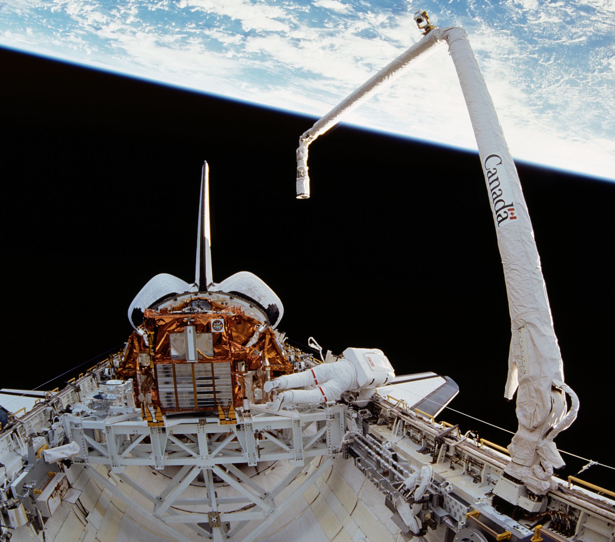
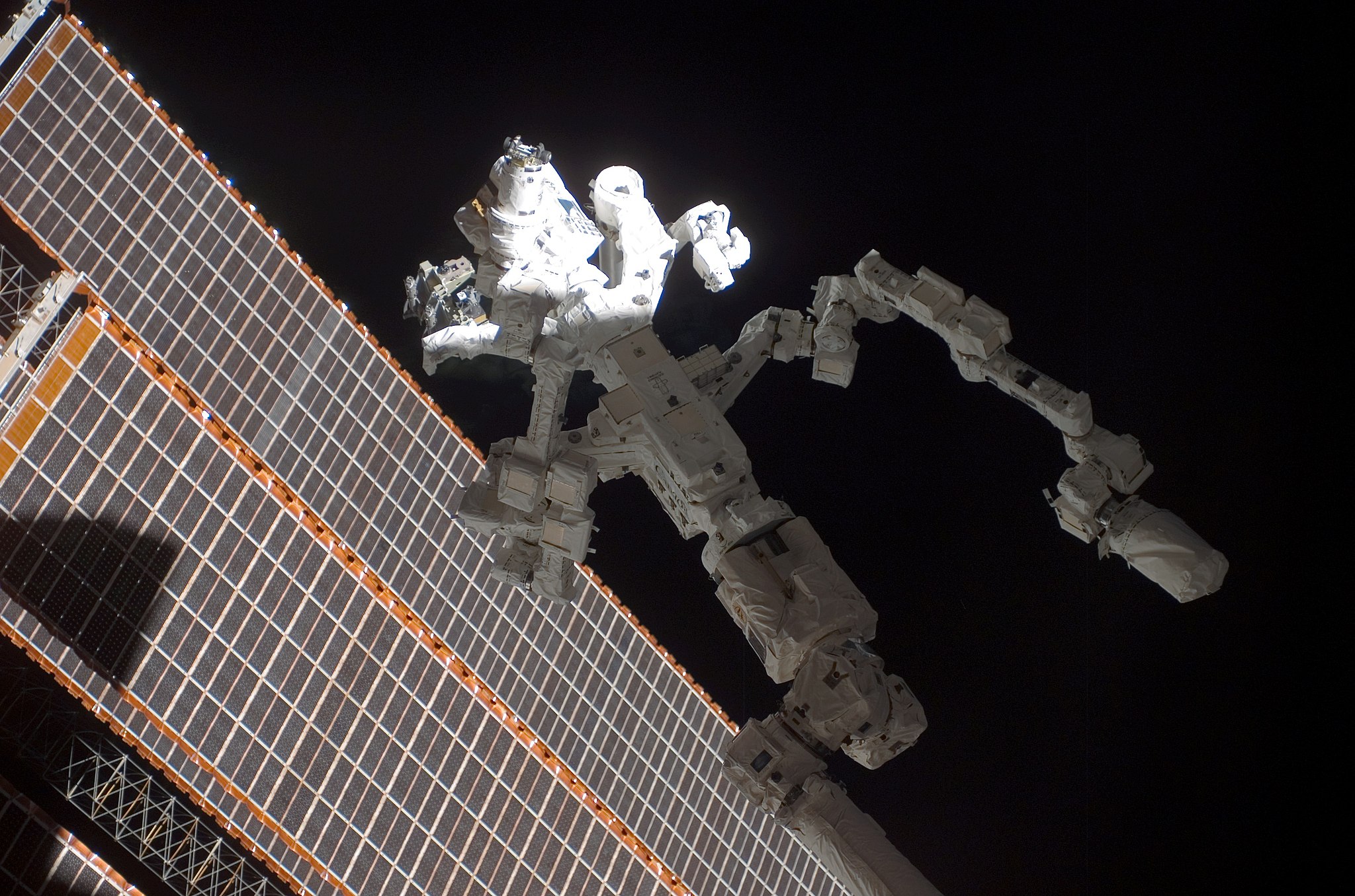
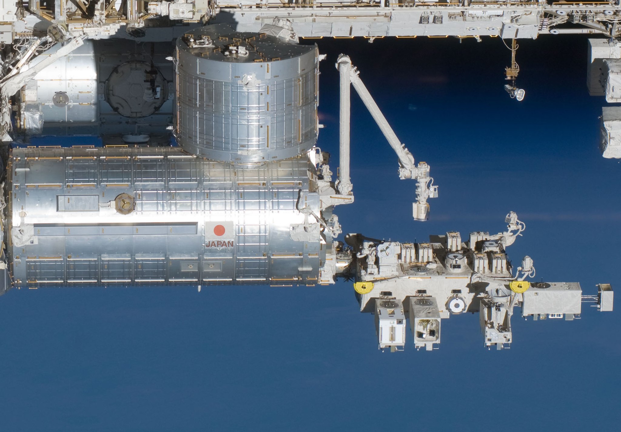
One of the first manipulator systems to be used in space was the Shuttle Remote Manipulator System (SSRMS) in 1981 (Bennett and Legler, 2011). It was designed to deploy, manoeuvre, and capture payloads and later also used for on-orbit inspection of the shuttle post Challenger accident. This started an era of robotic manipulators which assist in human spaceflight. The foremost example of this is the Mobile Servicing System (MSS) on the International Space Station (ISS) along with the Japanese Experiment Module Remote Manipulator System (JEMRMS). The MSS consists of the SSRMS Canadarm2, Mobile Remote Servicer Base System (MBS), and the Special Purpose Dexterous Manipulator Dextre. These robots are used in the daily operations of the ISS and assist astronauts in various tasks such as spacewalks, moving large modules and berthing supply spacecraft like the SpaceX Dragon and the Cygnus. The JEMRMS arm is used to support experiments on the exposed facility outside the Japanese Kibo module or carrying out maintenance on the Kibo module. These can be considered as primitive on-orbit servicing robots. They are always controlled manually, either by the astronauts or by ground-control.
In addition to the robots used on the ISS for assisting astronauts, 2 other satellite missions have been carried out successfully that have manipulator arm attached. The first is the Japanese Engineering Test Satellite No. 7 (ETS-VII) (see Oda Et al. 1996). It was launched in 1997. It carried a 2m long robotic arm with 6 rotational joints and was the first unmanned satellite to do so. The arm was teleoperated from the ground while it carried out various experiments such as autonomous rendezvous and docking, piloting the satellite remotely, and robot arm manipulation using the task board and the target satellite. This was also the first satellite to carry out experiments demonstrating reactionless manipulation where no reaction torques are transferred from the robot arm to the satellite.
In 2007, DARPA along with NASA launched the Orbital Express mission. Like the ETS-VII, it also consisted of a servicer satellite ASTRO and a target satellite NEXTSat. ASTRO satellite had a 6 Degree of Freedom (DoF) robot arm mounted on it using which it performed several experiments during its 4 month mission: autonomous capture of a free-flying client satellite NEXTSat, autonomous transfer of battery and computer On-Orbit Replaceable Units (ORUs), fluid transfer, and autonomous rendezvous, proximity operations and berthing.
Apart from these dedicated robotic demonstration missions and operational robots on the ISS, there have been several robotic experiments carried out in-orbit that focused on various technologies such as shared autonomy during the ROTEX mission (see Hirzinger, 1994) on Spacelab in 1993, Ground-to-Space low latency teleoperation and robotics component verification during the ROKVISS (see Hirzinger, Et al. 2005) mission on the ISS during 2005-2010, and space-to-ground low latency teleoperation with force-feedback in the KONTUR-2 (see Artigas, Et al. 2016) experiment on the ISS in 2016. Currently, the European Space Agency is operating the METERON experiment which includes force-feedback teleoperation, rover operations, and shared autonomy experiments (see Lii, Et al. 2015) which can be done for longer periods of time (over 1 hour) compared to previous experiments which used line of sight communication (<10 minutes). Some of the other current robotic experiments on the ISS are NASA’s SPHERES (see Miller, Et al. 2000) and Astrobee (see Bualat, Et al. 2015) programs.
Apart from the robots and robotic testbeds on ISS, one current commercial OOS mission underway is the MEV-1 mission from Northrop Grumman (News Link). This mission aims to extend the mission lifetime of the satellite Intelsat-901. This was launched on October 10, 2019 and will reach Intelsat-901 in about three and a half months. Furthermore, future OOS missions are planned such as NASA’s Restore-L mission (see Reed, Et al. 2016).
Mathematical Modeling of Rigid, Free-Floating Manipulator Systems
Here, a summary of the mathematical modelling is given. A comprehensive derivation can be found at Equations of Motion For Free-Floating Robots. Furthermore, a quaternion-based linearization method for the equations of motion can be found here.
Dynamics
Modelling of Space Robots is different from those used on Earth due to the fact that the base of the robot is not fixed. This causes the base to experience motion from the reaction forces of the movement of the robot arm. The free-floating dynamics of the spacecraft- manipulator system can be modelled using the following equation:
\[\begin{bmatrix} H_b & H_{bm} \\\ H_{bm}^T & H_b \end{bmatrix} \begin{bmatrix} \ddot{x_b} \\\ \ddot{\phi} \end{bmatrix} + \begin{bmatrix} c_b \\\ c_m \end{bmatrix} = \begin{bmatrix} F_b \\\ \tau \end{bmatrix} + \begin{bmatrix} J_b^T \\\ J_m^T \end{bmatrix} F_{ee}\]Here, the symbols are as follows:
$H_m$, $H_b$, $H_{bm}$ : Inertia Matrices of the manipulator, base, and the coupling between the base and the arm.
$x_b$ : Position/orientation of the base.
$\phi$ : Joint angles in the manipulator arm.
$c_b$, $c_m$ : Non-linear Coriolis and Centrifugal Forces.
$F_b$ , $\tau$ : Forces and Torques on the base (satellite).
$J_b$ , $J_m$ : Base and Manipulator Jacobian.
$F_{ee}$ : Forces on the end-effector.
Generalized Jacobian Matrix and Resolved Motion Rate Control
Since the movement of the arm exerts forces and torques on the base and this in return affects the position of the end-effector of the arm, the manipulator Jacobian does not provide the correct relationship between the joint velocities and the end-effector velocities. Due to this, a new jacobian called the Generalized Jacobian Matrix (GJM) was developed by Umetani and Yoshida in 1989 which takes into account the dynamics of the system and gives a relationship between joint and end-effector velocities. This jacobian is given from the following relationship:
\[\hat{J} = J_{m} - J_{b} H_{b}^{-1}H_{bm}\]Using this jacobian, a relationship between the joint and end-effector velocities can now be defined as (assuming initial end-effector velocity to be zero):
\[\dot{x}_{ee} = \hat{J}\dot{\phi}\]From this equation, the jacobian matrix can be inverted to find the joint velocities required to achieve a given end-effector velocity. This method of control is called Resolved Motion Rate Control (RMRC). While using the GJM along with the RMRC, the end-effector will follow the required trajectory even while the base translates and rotates.
Reaction Null Space
Sometimes, the rotation of the base is an undesirable motion due to various constraints such as fuel consumption, directional communication, thermal, solar panels, etc. For such cases, the robot control can be adapted to induce the zero torques on the base while executing motions. Such manipulator trajectory planning has been studied extensively and the following null-space solution can be derived from the dynamics equation given before:
\[\dot{\phi} = (E - \tilde{H}_{bm}^{+}\tilde{H}_{bm}) \dot{\zeta}\]Here, E is the identity matrix and zeta is an arbitrary vector with length equal to the number of links in the manipulator. Any joint velocities that satisfy the above equation will not induce any rotation to the free-floating base of the manipulator. The arbitrary vector zeta can be used to impose constraints on the path followed by the end effector while still keeping zero base rotation. It should be noted that while carrying out reactionless motion, the manipulator loses 3 DoF from its controllability of the end-effector. These are utilized for controlling base rotations. Thus, for a 7 DoF manipulator arm, the end-effector can only be controlled in 4 DoF in ideal conditions. Dynamic or Kinematic singularities might reduce this further.
Contact Dynamics
The chapter on contact dynamics of free-floating robotic manipulators for On-Orbit Servicing (OOS) nd Active Debris Removal (ADR) can be found here.
Available Modelling Tools and Software
Generally speaking, any programming language can be used to model the behavior of free-floating robots. However, Matlab/Simulink is one of the most popular tools used to analyze the dynamics and control of space robots. To prevent duplication of efforts, the most basic computations such as the robot and base satellite’s inertia matrices, jacobians etc.. are performed by most robot simulation libraries. Some of the robot simulation tools/libraries are given here:
- Robotics Toolbox (Corke, P.I. 1996): Robotics toolbox is the brainchild of Peter Corke. This was one of earliest (and currently most mature) open-source toolboxes available in Matlab for simulation of robots. It gives tools for representing the Kinematics and Dynamics of serials robots in either 2D or 3D. It also supports various robot motion models, path planning algorithms, localization algorithms, and integration with simulink.
- RoboPy Dua, A. (Github): Robopy is the Python 3 implementation of the Robotics Toolbox by Peter Corke. It does not require Matlab to run. Instead, it uses open source libraries such as VTK, Numpy, and SciPy.
- Webots (Michel O, 1998): Webots is a free and open-source robot simulation tool developed initially at EPFL, Switzerland. It supports wide varieties of robot models along with CAD model import. It uses the Open Dynamics Engine (ODE) to simulate the kinematics, dynamics, inertia, friction, etc. accurately. It supports Mac, Windows, and Linux operating systems and allows for cross-compatibility using standardized robot model descriptions. Furthermore, it has APIs for various languages such as Python, C/C++, ROS, and Matlab.
- Pinocchio (Carpentier, Et al. 2019): Pinocchio is developed by CNRS in France for multi-body simulation in C++ and Python using fast and efficient rigid body dynamics algorithms. It is a free and open-source library and supports linux and macintosh operating systems. It contains tools for visualizing the robot, plotting data etc.
- DRAKE (Tedrake R, Et al. 2019): DRAKE is C++ robot simulation toolbox developed by MIT. It aims to simulate complex dynamic phenomenons such as aerodynamics, friction, contact, etc. while exposing the model clearly to the user. It supports Python and Julia programming languages.
- MARS (DFKI): MARS (Machina Arte Robotum Simulans) is a robotics simulation tool developed at DFKI. It supports Windows, Mac, and Linux. It includes tools for visualization using Qt, and the physics are simulated using ODE.
- Gazebo (Koenig, N Et al. 2004): Gazebo is an open-source 3D robot simulation software which supports multiple physics engines such as ODE, Bullet, Simbody, and DART. It includes tools for modelling, programming, simulation, and visualization. Along with this, it also has tools for training AI systems based on data generated from the simulations. It is one of the most used robot simulation tools in the Robot Operating System (ROS). It also includes features such as generating data (with noise) from simulated sensors, modular systems, and cloud simulation. It has been used as the simulation environments for various robotics competitions such as the DARPA Robotics Challenge.
- ReDySim (Shah Et al. 2012): Recursive Dynamics Simulator (ReDySim) is a Matlab solver for robotic systems. It can perform inverse and forward dynamics of both fixed and floating robot systems with rotary and prismatic joints. Furthermore, it has a symbolic module capable of generating equations of motion for floating robot systems in symbolic form. It is a closed-source software with predefined APIs for usage.
- SPART (Virgili-Llop Et al. 2016): Space Robotics Toolkit (SPART) is an open-source dynamics solver for free-floating robots in Matlab/Simulink. The toolbox is modular and supports code generation from Matlab and Simulink which makes it easy to integrate with experiments/tests. Furthermore, it includes tools for robot control and workspace analysis.
Microgravity Simulation Methods
Various methods to test the developed algorithms and control of free-floating robots are available. Each has its advantages and disadvantages based on various factors such as cost, workspace, fidelity, and experiment duration. The decision to use any of these methods is driven by budget, manpower, hardware availability and the level of fidelity required for that certain test. As an example, a test for high-speed contact dynamics may not be carried out either in software or on a robot testbed as the software does not offer enough realism and the robot feedback loop is not fast enough. Hence, the other options would be the either the Air bearing testbed, underwater, or parabolic flight. As the contact is at high speed, then the underwater testbed cannot be used due to hydrodynamic effects at high speed. If 2D test is sufficient, air bearing testbed seems to be the best option for this test. Parabolic flight offers high fidelity test capability for this test but only for short durations of time.
Below, some of the most used methods are given along with a comparison carried out in the following table:
- Software Simulation: The easiest way to simulate free-floating robots is via software simulation. Tools such as Matlab/Simulink, Gazebo, etc.. make it relatively easy and cost-effective to develop and test control strategies for manipulators with free-floating bases. However, software simulations generally are of lower fidelity than physical experiments. This is due to inaccurate modelling of friction, inertia, contact etc. The strengths of software simulation lie in its cost-effectiveness and that the simulations have no limitations on experiment time and workspace. Both ReDySim and SPART come with example simulations of free-floating robots.
- Robot testbed: It is possible to simulate the motion of a manipulator attached to a free-floating base by fixing the system on a robot arm. The robot arm can simulate free-floating dynamics by sensing the reaction forces/torques and compensating for gravity. However, these compensations are only possible for the base. The manipulator will need to have its own gravity compensation method.
- Parabolic Flights: Parabolic flights offer zero-g environments for short durations (<1min) by flying the aircraft in specific parabolic manuevers. Each flight consists of multiple parabolas which can bring the total experiment time to over 10 minutes. However, during each parabola, it is difficult to set up the experiment with the required initial conditions i.e the initial motion of the floating base. Thus, experiments which are sensitive to initial conditions are difficult to perform in such short times. However, for experiments which are independent to initial conditions, parabolic flights offer a cost-effective way of testing in 3D free-floating conditions.
- Air bearings/Flat floors: Air bearing testbeds are the most common way to test free-floating robots. The robots are placed on a platform which is floating over a smooth level surface by the use of air bearings. This is similar to an inverted air hockey table. The cushion of air provides a low-friction surface over which the robotic spacecraft can move freely. Since the setup is on a flat floor, this limits the frictionless movement of the robot to 2D. Spherical air bearings have been used in some of the setups to add additional roll, pitch, and yaw DoF (this could be called 2.5D or 5DoF). No linear movement in the direction of gravity (Z-direction) is possible. This method gives a large workspace for the robot as well as experiment times of up to 30mins depending on the air capacity of the platform.
- Underwater: Underwater testbeds are the most common method of training astronauts for the microgravity environment and Extra-Vehicular Activities (EVAs). These can also be used to test and develop control strategies for free-floating robots. By achieving neutral buoyancy, the spacecraft and the manipulator can be tested in free-floating conditions as the effects of gravity are negated by the buoyant forces. These testbeds provide realism as similar hardware can be used and realistic forces are included in the testing. However, the hydrodynamic effects of the surrounding water have to be considered.
- Space Based Testbeds: Various satellites such as ETS-VII and Orbital Express have been launched already for testing robot control methods in space. Furthermore, the ISS also has robotic testbeds such as Spheres and Astrobee which can be used by researchers all around the world to test their algorithms. Astrobee even allows roboticists to send hardware that can then be attached and tested in the ISS. Testing in space gives the most realistic scenario for developing control strategies but this comes at a very high cost and risk penalties.
The table below summarizes the comparison of various testing methods for space robots:
| Simulation Method | Cost | Experiment Duration | Fidelity | External Forces | Workspace |
|---|---|---|---|---|---|
| Software Simulation | Low | Infinite | Low | Can be modeled. Not necessarily realistic | Infinite |
| Robot Testbed | Low | Infinite | Low | Can be modeled in Software or with Force-Torque Sensor | Limited to robot workspace |
| Parabolic Flight | Medium | Short Duration (<1min) | High | Realistic | Limited to Aircraft Used |
| Air bearings Flat Floor | Medium | Medium Duration (10-30mins) Limited by Air Capacity | Medium (2D/2.5D) | Semi-Realistic. Only in 2D/2.5D | Limited by floor space and cost |
| Underwater | High | Long Duration Possible | Medium. 3D but water has viscosity and drag | Semi-realistic due to fluid interactions | Limited to water tank/pool size |
| Space (Eg. ISS) | Very High | Long Duration Possible | High. Realistic | Realistic | Infinite in Orbit or Limited to the Workspace of ISS |
References
[Kaplan, 2009] Kaplan, Marshall, Survey of space debris reduction methods, AIAA space 2009 conference & exposition, 2009.
[Bennett and Legler, 2011] D. Legler, Robert and V. Bennet, Floyd, Space Shuttle Missions Summary, NASA Johnson Space Center, 2011.
[Hirzinger, 1994] Hirzinger, G., ROTEX—the first space robot technology experiment, In Experimental Robotics III (pp. 579-598). Springer, Berlin, Heidelberg. 1994.
[Hirzinger, Et al. 2005] Hirzinger, G., Landzettel, K., Reintsema, D., Preusche, C., Albu-Schaeffer, A., Rebele, B. and Turk, M., Rokviss-robotics component verification on ISS. In Proc. 8th Int. Symp. Artif. Intell. Robot. Autom. Space (iSAIRAS). Munich, 2005 p. Session2B.
[Artigas, Et al. 2016] Artigas, J., Balachandran, R., Riecke, C., Stelzer, M., Weber, B., Ryu, J. H., & Albu-Schaeffer, A. Kontur-2: force-feedback teleoperation from the international space station. 2016 IEEE International Conference on Robotics and Automation (ICRA). IEEE, 2016.
[Lii, Et al. 2015] Lii, N.Y., Leidner, D., Schiele, A., Birkenkampf, P., Pleintinger, B. and Bayer, R., Command robots from orbit with supervised autonomy: An introduction to the meteron supvis-justin experiment. In Proceedings of the Tenth Annual ACM/IEEE International Conference on Human-Robot Interaction Extended Abstracts (pp. 53-54). ACM. 2015.
[Miller, Et al. 2000] Miller, D., Saenz-Otero, A., Wertz, J., Chen, A., Berkowski, G., Brodel, C., Carlson, S., Carpenter, D., Chen, S., Cheng, S. and Feller, D., SPHERES: a testbed for long duration satellite formation flying in micro-gravity conditions. In Proceedings of the AAS/AIAA space flight mechanics meeting (pp. 167-179). Clearwater, Florida, January. 2000.
[Bualat, Et al. 2015] Bualat, M., Barlow, J., Fong, T., Provencher, C. and Smith, T., Astrobee: Developing a free-flying robot for the international space station. In AIAA SPACE 2015 Conference and Exposition (p. 4643). 2015.
[Shah Et al. 2012] Shah, S.V., Nandihal, P.V. and Saha, S.K. Recursive dynamics simulator (ReDySim): A multibody dynamics solver. Theoretical and Applied Mechanics Letters, 2(6), p.063011. 2012.
[Virgili-Llop Et al. 2016] Virgili-Llop, J., Drew, D.V., Romano, M., Hobson, G.V., Wakefield, B.E. and Roberts, W.B., 2016. SPACECRAFT ROBOTICS TOOLKIT: AN OPEN-SOURCE SIMULATOR FOR SPACECRAFT ROBOTIC ARM DYNAMIC MODELING AND CONTROL. In 6th International Conference on Astrodynamics Tools and Techniques. 2016.
[Corke, P.I., 1996]. Corke, P.I., A robotics toolbox for MATLAB. IEEE Robotics & Automation Magazine, 3(1), pp.24-32. 1996. Website
[Michel, O., 1998] Michel, O., Webots: Symbiosis between virtual and real mobile robots. In International Conference on Virtual Worlds (pp. 254-263). Springer, Berlin, Heidelberg. 1998. Website
[Carpentier, Et al. 2019] Carpentier, J., Saurel, G., Buondonno, G., Mirabel, J., Lamiraux, F., Stasse, O. and Mansard, N., The Pinocchio C++ library: A fast and flexible implementation of rigid body dynamics algorithms and their analytical derivatives. In 2019 IEEE/SICE International Symposium on System Integration (SII) (pp. 614-619). IEEE. 2019. Website
[Tedrake R, Et al. 2019] Russ Tedrake and the Drake Development Team. Drake: Modelbased design and verification for robotics. MIT. 2019
[Koenig, N Et al. 2004] Koenig, N. and Howard, A., 2004. Design and use paradigms for gazebo, an open-source multi-robot simulator. In 2004 IEEE/RSJ International Conference on Intelligent Robots and Systems (IROS)(IEEE Cat. No. 04CH37566) (Vol. 3, pp. 2149-2154). IEEE. 2004. Website
[Umetani and Yoshida in 1989] Umetani, Yoji, and Kazuya Yoshida. Resolved motion rate control of space manipulators with generalized Jacobian matrix. IEEE Transactions on robotics and automation, 5(3), pp.303-314. 1989.
[Oda Et al. 1996] Oda, M., Kibe, K. and Yamagata, F. ETS-VII, space robot in-orbit experiment satellite. In Proceedings of IEEE international conference on robotics and automation (Vol. 1, pp. 739-744). IEEE. 1996.
[Reed, Et al. 1994] Reed, Benjamin B., Robert C. Smith, Bo J. Naasz, Joseph F. Pellegrino, and Charles E. Bacon. The restore-L servicing mission. In AIAA SPACE 2016, p. 5478. 2016.
Psst: Since all uncrewed Spacecraft are called “Robotic Spacecraft” Sputnik was technically the first robot in space!